nicole@portfolio:~/projects/rc-power$ cat README.md
Embedded RC Power System
Designed a custom PCB and physical housing for selective power cycling of onboard electronics for the Cornell Autonomous Sailboat project team.
KiCad · PCB Design · Arduino
Overview
During field testing, a remote-control power distribution system aims to improve recovery efficiency from subsystem faults while also eliminating delays caused by manually resetting onboard electronics.
Implementation
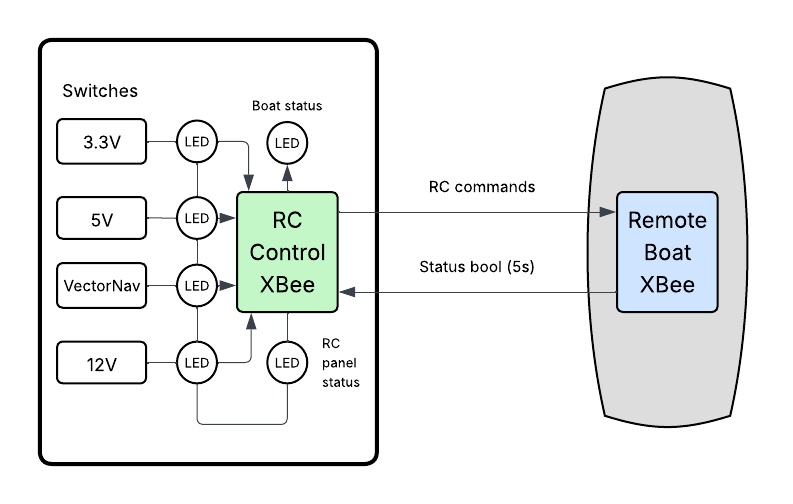
The control panel continuously monitors system status while transmitting commands to the boat that toggle power to specific subsystems. It is microcontroller-based, using an Arduino Nano, and communicates through serial commands sent via XBee radio modules. The user interface primarily consists of switches and LEDs that indicate system power, communication status, and subsystem states, as modeled in the breadboarded circuit below.
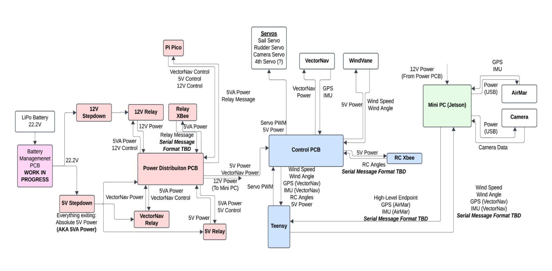
Four digital input pins on the central Nano controller, corresponding to switches, are compared against their previous states to detect changes. If a change is detected, a serial command is sent to the XBee instructing the boat to shut down a specific system. Sequential communication transmissions and short delays between them reduce the risk of communication overlap. The Nano also checks for periodic status signals from the boat. If the shutdown button is pressed, all systems are set to a latched-off state that persists until the system is reset.
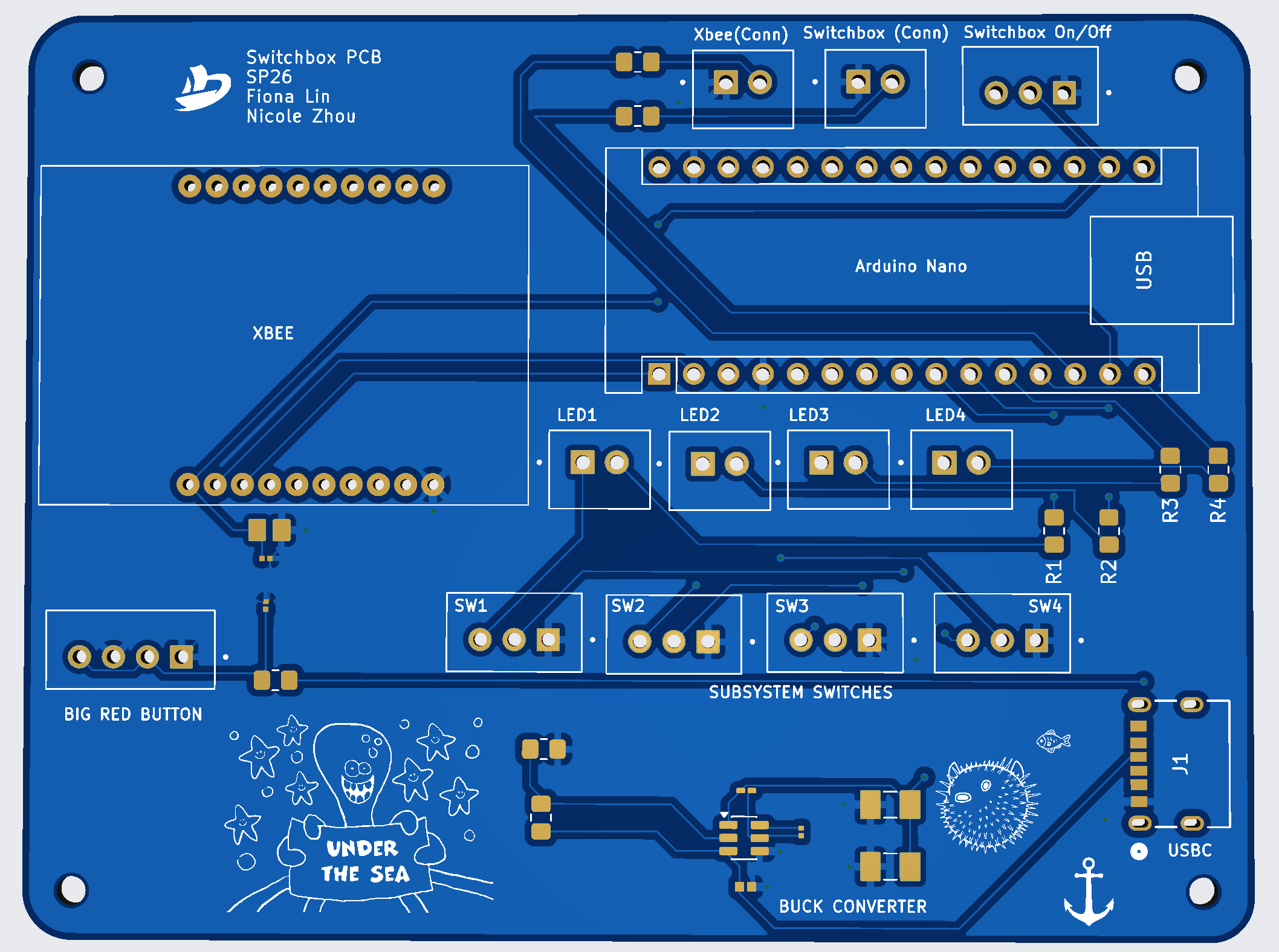
A custom circuit board ordered through JLCPCB was also designed to integrate all components. The traces and footprints are shown below. We also included a buck converter between the USB header and the Nano to satisfy the system's power constraints.